Design and simulation of solar inverter
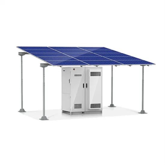
This report presents a detailed simulation of a solar photovoltaic (PV) inverter system using PSIM software. The system includes six PV panels, a DC-DC boost converter, an inverter bridge, and a closed-loop control circuit. The inverter's various components have been tested with MATLAB Simulink. There are two kinds of loads that are employed. . hat AC load needs to convert DC to AC so that it requires solar inverter. ABB's Universal Framework simulation tool can be used in various simul energy generation is set to continue in the years to come. The main using the classical proportional integral (PI) and the. . [pdf]
Microgrid line impedance simulation system
This paper proposes an enhanced control for a converter based three phase line impedance emulator in order to improve clean energy sources integration. In fact, the proposed emulator is used to perform tests r. [pdf]FAQs about Microgrid line impedance simulation system
Can virtual impedance improve the stability of dc microgrid?
Zhu, X., Han, D., and Meng, F. (2019). A method of series virtual impedance of grid-connected converters to improve the stability of DC microgrid. Power Grid Technol. 43 (12), 4523–4531. doi:10.13335/j.1000-3673.pst.2018.1752 Keywords: island operation mode, adaptive virtual impedance, power control, voltage drop, stable operation
Does line impedance identification improve droop control strategy in microgrid?
Electr Eng 102:267–278 Chen XQ, Jia HJ, Chen SY (2017) Improved droop control strategy based on line impedance identification for reactive power sharing in microgrid. High Volt Eng 43 (4):1271–1279
What causes mis-match of line impedance in a microgrid?
In the islanded microgrid structure, the mis-match of line impedance between the Distributed Generation (DG) units and imbalance of inverter local load are two critical factors to be dealt with carefully.
What is a simulation model of a microgrid?
The simulation model consists of two DGs operating in parallel to supply linear loads. And the load parameter is P 1 = 20 k W, Q 1 = 20 k V a r; P 2 = 10 k W, Q 2 = 10 k V a r. FIGURE 8. Simulation model of islanded microgrid.